Inscrivez-vous pour débloquer vos prix B2B exclusifs et commencez vos achats. Inscrivez-vous maintenant!
RS485 bus communication interface
Commande uniquement
Prix (hors TVA):
75,52 €
EAN: 4010312315651
MPN: 30014065
Colis: 1
Délai de livraison estimé à notre entrepôt (environ):
2-4 weeks
Technical Information
| État de l’article | Nouveau |
| Nom du fabricant | RS485 bus communication interface |
| Marque | ELTAKO |
| Catégories |
Bus System Devices (KNX/Modbus)
|
| Pays d’origine* | CN |
| * The actual country of origin may differ depending on the delivery batch. To confirm the specific country of origin, please contact your account manager. | |
| Code du système harmonisé | 8526 9200 00 |
| Système de bus KNX | No |
| Système de bus radio fréquent | Yes |
| Autres systèmes de bus | Autre |
| Système de bus KNX radio | No |
| Fréquence radio bidirectionnelle | Yes |
Détails d’emballage
| Niveau d’emballage 1 | 4010312315651, 4010312315651 |
| Niveau d’emballage 2 | 4010312315651 |
| Niveau d’emballage 3 | 4010312315651 |
Autres données techniques
| Méthode de montage | DRA (adaptateur pour rail DIN) |
| Système de bus Powernet | No |
| Type de fixation | Montage par serrage |
| Largeur en nombre d'espacements modulaires | 2 |
| Système de bus LON | No |
| Degré de protection (IP) | IP20 |
| Nombre de points d'actionnement | 10 |
Téléchargements
Description
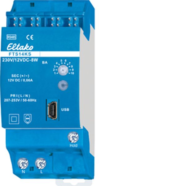
FTS14 communication interface for the Eltako RS485 bus with enclosed power supply FSNT14-12V/12W. Only 0.4 watt standby loss. Modular device for DIN-EN 60715 TH35 rail mounting. 1 module = 18mm wide, 58mm deep. Supply voltage 12V DC. Connection to the Eltako RS485 bus. Bus wiring and power supply with jumpers. The delivery includes 1 power supply FSNT14-12V/12W, 1 spacer DS14, 2 terminators with printing Ω, 1/2 module, 3 jumpers 1 module (including 1 spare), 1 jumper 1,5 TE, 2 jumpers 1/2 module (including 1 spare) and 1 jumper installation tool SMW14. If the power supply is subjected to a load of more than 4W, a ventilation distance of ½ to neighboring devices must be maintained on the left side. With a load greater than 6W, a ½ ventilation gap is also required between the FSNT14 and the FAM14 with the DS14 spacer. A DS14 spacer and a long jumper are therefore included. If the total power requirement of a series 14 bus system is higher than 10W, an additional FSNT14-12V/12W must be used for every 12W of additional power. Optionally, 12V DC can also be supplied at the GND/+12V terminals. Connection to the Eltako-RS485 bus. Bus cross wiring and power supply with jumper. The attached second terminator should be plugged to the last actuator. Mini USB to connect to a PC, to create an equipment list, to configurate the actuators using the PC tool PCT14 and for data backup. A legalization code to download the PCT14 from the Eltako homepage www.eltako.de is included in the FTS14KS. All FTS14EM and if needed gateways FGW14 will be connected to the terminal Hold when they connect a PC with a RS232 bus. According to the operating manual 10 different operating modes can be set with the operating mode rotary switch BA. The bottom LED lights up green if a connection from the PC tool PCT14 was created. When reading or writing date the LED flashes green. The green LED goes out if the connection from the PC tool PCT14 was terminated.

