SIMET Lighting protection



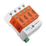
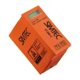
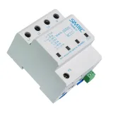
simet lighting protection Scope and use cases
Facilities that sit under exposed roofs, PV arrays, and long exterior cable runs need a coordinated scheme that handles both direct strikes and switching surges. Simet offers enclosure-ready components for main boards, sub-DBs, façade risers, and PV combiners, with published Iimp/In/Up figures so designers can close the protection study against EN 62305 and IEC 61643 without guesswork. Field crews get pluggable cartridges, remote contacts for SCADA, and clear torque tables that actually match real cable sizes.
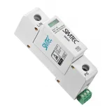
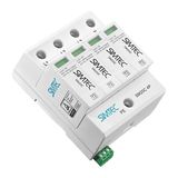
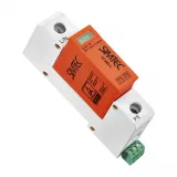
simet surge protection devices Types and ratings
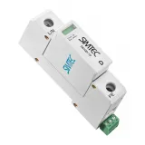
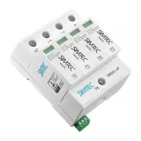
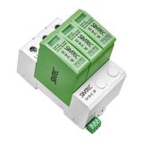
Type 1 devices with 10/350 µs waveforms handle partial lightning currents at service entrances (typical Iimp 12.5–25 kA per pole, UC 255/275 V AC). Type 2 units protect distribution boards with 8/20 µs In of 20–40 kA and Up ≤1.5–1.8 kV for 230/400 V networks. Type 3 plug-side protection cleans up residuals at sensitive loads. MOV or MOV+GDT hybrid paths limit follow current on TN/TT systems; internal thermal disconnectors and visual flags indicate end-of-life. PV strings use 600…1500 V DC units (IEC 61643-31) with polarity-safe terminals and high-temperature bodies for rooftop boxes.
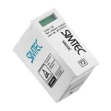
simet spd modules Coordination and wiring
Stage T1→T2→T3 so the let-through of the upstream device never overstresses the next. Keep leads short and parallel; aim for ≤0.5 m total path L–PE and N–PE, or use V-connection kits to halve inductive overshoot. Backup fusing is declared by frame—coordinate with upstream MCB/ fuses to avoid nuisance clearing during surge events. Remote OF/SD contacts report “healthy/tripped” to BMS/SCADA so maintenance can swap cartridges during planned windows.
simet lightning arresters Roof and mast interfaces
Air terminals, bases, and conductors form the external LPS per EN 62305-3. Choose aluminum or copper tape (e.g., 30×3.5 mm) or 16–50 mm² round, with tested clamps over ridge tiles and parapets. Test joints at down-conductor bases simplify periodic measurements; strike counters and insulated stands help when the separation distance “s” is tight near rooftop plant. Entry plates bond the down-conductor to the internal equipotential bar with low impedance and corrosion-matched hardware.
Technical specifications and standards
Conformity: IEC/EN 61643-11 (low-voltage SPDs), IEC 61643-31 (PV DC), EN 62305 (risk assessment and LPS), EN 60364-4-44 / 5-54 (earthing and bonding). Environmental: −40…+80 °C operating on outdoor parts, IP20 inside boards, IP54–IP66 for sealed kits. Terminals typically 2.5…35 mm² Cu; torque and strip lengths are printed on the label. Coordination data includes maximum prospective short-circuit current at the point of installation and required upstream protection.
Applications, layouts, and compatibility
Main incomer: Type 1 on TN-C-S/TN-S services near exposed feeds or building LPS. Floor DBs: Type 2 with Up compatible to equipment impulse withstand (typically 2.5 kV for distribution). PV: string-level DC units at combiners, AC Type 2 at the inverter output. Data/controls: RJ45/coax/RS-485 protectors where long runs enter the cabinet; keep protectors bonded within the same equipotential zone as the power SPD.
Integration with distribution and controls
In SENTRON/other DIN boards, SPDs sit on dedicated plates with short PE jumpers to the bar; route neutral through the declared path on TT to maintain disconnector logic. Tie OF/SD to PLC inputs for alarm and maintenance counters. For VFD rooms, use EMC glands and bond the SPD earth direct to the primary PE bar; avoid daisy-chained earths that add impedance.
Selection guide for B2B buyers
- Run the EN 62305 risk check to decide if Type 1 is mandatory; otherwise start at Type 2.
- Match UC to the system (230/400 V AC, IT/TN/TT specifics) and verify Up against equipment impulse ratings.
- Confirm In/Imax against local keraunic level and feeder length; oversize where risers are long.
- Coordinate backup fuses, SCCR, and SPD short-circuit withstand at each board.
- For PV, choose polarity, UCPV, and temperature class; keep polarity diagrams in the lid.
Where a spec line calls for simet overvoltage protectors, include UC, In/Iimp, Up, mode of protection, and backup fuse so procurement cannot substitute consumer-grade parts.
Grounding, bonding, and hardware
Keep the main equipotential bar near the service entry; bond water/gas/HVAC metallics there. Use tinned copper bars, crimped lugs, and marked test links. Rods (copper-bonded or stainless) and clamps should match soil chemistry; measure Ra and document with seasonal checks. For kits labeled simet grounding accessories, specify bar size, hole pitch, rod type/length, clamp alloy, and conductor cross-section on the tag.
System scope and documentation
Large campuses benefit from single-line overlays that show SPD class, UC/Up, and inspection intervals across all boards—treat this as part of simet electrical protection systems so FM teams know exactly what to check after storms. Store cartridge part numbers, spare counts, and torque sheets with the DB schedule.
Advantages of working with Bankoflamps
We align T1/T2/T3 staging, UC/Up targets, PV DC ratings, earthing hardware, and remote-contact needs to your one-lines and risk study, then display live EU stock by warehouse before shutdown windows are locked. Quotes usually land in about an hour with EAN/MPN, Iimp/In/Up, backup-fuse data, torque tables, and bar kits spelled out—so selections don’t drift mid-phase. Your portal shows lead times, consolidated shipment status, and downloadable price lists with validity dates; approved clients can use post-payment up to 30 days. We batch by incomer, floor DB, and PV combiner to cut freight and site sorting, and your account manager cross-checks fault level, bonding path, gland strategy, conductor size, and SCADA signaling against your drawings—so crates arrive board-ready and electricians terminate once.