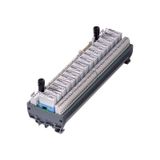
TE Connectivity Relays
Project teams use TE components to stabilise switching logic between PLC outputs and field loads. The portfolio covers slim 6.2 mm modules and higher-power housings with clear marking, LED indication, and test levers. Coil systems span 12 V, 24 V, 48 V DC and 110 V, 230 V AC; contact sets reach 6 A, 10 A, and 16 A in SPDT and DPDT formats. Typical operating windows are −40…+70 °C, with coil suppression built in or available as plug-in elements to keep PLC transistor outputs safe from back-EMF.
te connectivity relays for panel and field control
Use plug-in electromechanical units where galvanic isolation and low on-state loss are required. Contact materials (AgNi, AgSnO2) are selected to match inductive or lamp loads; expected life exceeds 1×10⁶ mechanical cycles with proper arc management. Creepage and clearance are sized for 250–440 V networks, and coil power is typically 0.4–0.9 W to minimise cabinet heat. For procurement consistency across floors and risers, standardise part codes for te connectivity relays in the panel schedule and lock the coil voltage per zone.
te connectivity interface relays and signal adaptation
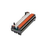
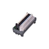
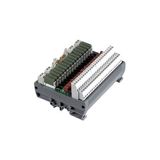
Slim interface modules bridge PLC I/O to actuators, offering test buttons, mechanical flags, and removable jumpers for commoning. Push-in bases accept ferruled fine-strand conductors 0.5…2.5 mm²; spring-clamp versions help in high-vibration areas. Typical release time is <10 ms, allowing clean hand-off of quick signals. Use te connectivity interface relays to translate 24 V control into mains-rated contacts without redesigning terminal layouts.
te connectivity solid state relays for silent switching
SSR variants eliminate contact bounce and acoustic noise; zero-cross types limit inrush on resistive loads, while random-turn-on supports phase-angle control. Expect leakage currents in the milliamp range and on-state voltage drops around 1.2–1.6 V, so plan heat paths accordingly. dv/dt immunity figures above 500 V/μs reduce false triggering in noisy cabinets. Where high cycle rates or dust make electromechanical contacts impractical, specify te connectivity solid state relays with clip-on heat sinks and thermal pads.
te connectivity industrial relay modules with diagnostics
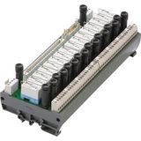
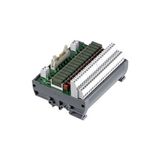
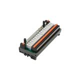
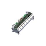
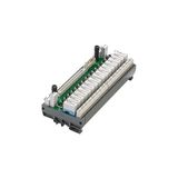
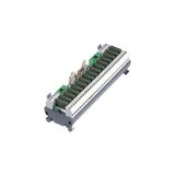
Pre-assembled relay modules combine the coil, base, LED, and protection network on a DIN footprint. Many offer blown-fuse indication, fuse pullers, and status grouping for quick inspection during night shifts. Input options include logic-level coils for direct PLC drive and wide-range coils with polarity protection. For repetitive room bundles, document te connectivity industrial relay modules by I/O type, fuse rating, and jumper scheme so carton contents mirror room drawings.
te connectivity relay sockets and wiring bases
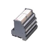
Sockets define wiring speed and serviceability. Options include screw, push-in, and spring clamps; marker channels take 6–12 mm labels that survive solvent wipes. Side jumpers allow common coil or common contact schemes without loose wires, and ejector levers prevent bent pins during swaps. Where mixed loads share a row, choose keyed footprints so only the correct relay fits the base. Crews usually stock te connectivity relay sockets by coil voltage family and pole configuration to keep maintenance predictable.
te connectivity control relays in automation loops
Control relays coordinate interlocks, pump alternation, and fan staging. Use mechanical latch or twin-coil types where state retention after power loss is needed. For motor starters, interposing relays protect delicate PLC outputs from the coil surge of contactors. Specify arc-suppressing RC modules on AC coils and flyback diodes on DC coils to extend contact life. In HVAC and lighting panels, planners assign te connectivity control relays to each functional block so diagnostics stay consistent across identical floors.
te connectivity din rail relays for compact cabinets
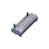
6.2–12.7 mm slimline bodies maximise I/O density on 35 mm rails and keep airflow clear in shallow enclosures. Many units provide removable spacers to maintain cooling gaps for SSRs. Clip strength is rated for transport vibration; end stops stop migration along the rail during service. When ceiling zones are tight, te connectivity din rail relays keep control logic local to the luminaire or damper without growing the junction box.
Product range and series overview
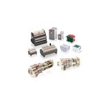
Form factors include plug-in cube, slim blade, and encapsulated SSR packages; contact sets span 1CO, 2CO, and power SPST; input coils cover DC and AC bands; accessories include coded jumpers, retaining clips, marker tags, and clip-on RC or diode modules. Typical test points permit live checks without removing the relay, and LED colours distinguish coil voltage families to avoid mix-ups during commissioning.
Technical specifications and selection points for engineers
Match coil burden to PLC sink/source capability; keep ≥20 % margin on output current. Derate contacts for AC-15 or DC-13 loads and consider inrush multipliers for LED drivers and transformers. For SSRs, calculate thermal rise with ambient plus enclosure delta-T; add heat sinks when continuous current approaches the nameplate. Choose AgSnO2 for inductive loads, gold-flashed contacts for <100 mA signals, and verify insulation category vs your overvoltage environment. Where EMC is critical, route coil returns away from high-dI/dt conductors and use bases with integrated suppression.
Applications and compatibility
Office cores and hotels benefit from slim interposing rows above lighting controllers; plant rooms use fused modules to protect field circuits; façades and parking decks prefer sealed SSRs for quiet operation; process skids need spring-clamp bases to resist vibration. Systems align with TE terminal blocks, plug connectors, and cable management so pitch, labeling, and torque values remain uniform when panels are expanded later.
Advantages of working with Bankoflamps
We align our workflows to your commissioning windows. Project quotes with EAN and MPN arrive in about an hour, and EU stock is shown live so crews are booked only when parts are real. Your portal provides shipment tracking, lead times, and downloadable price lists with validity periods that hold your budget line. Trusted accounts can work on post-payment up to 30 days. We consolidate partials to cut freight and a dedicated manager checks coil voltages, contact ratings, base types, jumper schemes, and heat-sinking against your drawings for deliveries across France, the Baltics, Germany, Spain, Italy, Belgium, and the Netherlands.
