Spelsberg E-mobility
spelsberg e mobility hardware map and use-cases
Spelsberg focuses on tough outdoor housings and modular internals that let you build AC Mode 3 points fast and keep them serviceable. Typical nodes are 1-/3-phase 230/400 V AC, 16–32 A per outlet (3.7/7.4/11/22 kW). Enclosures land IP54–IP65, IK08–IK10 with UV-stable PC/ABS or GEOS polycarbonate. Working window −25…+55 °C; gaskets and drain/vent options handle condensation. Socketry is Type 2 per IEC 62196-2 with shutter and mechanical lock; EVSE control follows IEC 61851-1. Protection stacks usually combine Type A RCD + 6 mA DC detection (IEC 62955) or a Type B RCD. Add Type 2/SPD in the feeder per the site’s lightning category.
AC hardware — spelsberg ev chargers and wall components
Wall sets pair a sealed body, Type 2 outlet (or tethered lead), a controller board (CP/PP pilot), and service-friendly distribution inside. For 11/22 kW, plan 5G4…5G10 mm² feeders, PF ≥ 0.98 on the EVSE PSU, THD ≤ 15 % where metering shares the cabinet. Cable entry M25/M32, stainless fixings, and padlockable service doors are standard on outdoor variants. Optional MID meters (EN 50470) sit under a clear window so reads are possible without opening. Load-shedding relays and contactors mount on 35 mm rail; a kWh pulse or Modbus RTU/TCP output is common for BMS.
spelsberg wallbox chargers (single and twin)
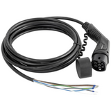
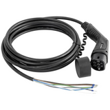
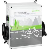
Single-outlet housings keep depth low for corridor and façade installs; twin bodies add segregated cavities so each outlet has its own RCD/MCB pair. Door interlocks and keyed isolators meet safe-maintenance rules. Cable management plates guide a 5 m tether without kinks; molded strain-relief and replaceable grommets protect jackets. RFID readers (13.56 MHz) and OCPP-capable gateways are panel-mounted behind UV-stable windows; keep RF clear of large busbars to avoid read range loss.
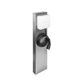
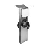
Pedestals and site gear for spelsberg car charging stations
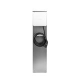
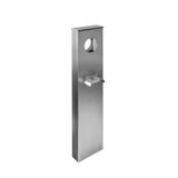
Freestanding posts use powder-coated steel frames with PC heads (IP54/IP65) and IK10 fronts for public zones. Bases accept M12 anchors; through-plinth ducting separates power and data. Twin-sided variants back-to-back two outlets for 2×22 kW on one foundation, with independent metering. Optional bollard sleeves add impact buffer; LED status rings around the socket carry state (ready/charging/fault) visible in daylight.
Electrical core and protection stack
Incoming isolation (60947-3) precedes a Type 2 SPD, then MCB/RCBO per outlet. For 32 A circuits, select C-curve with magnetic headroom for inrush when contactors pull in. Residual strategy: either RCBO Type A plus 6 mA DC module per outlet, or a single Type B feeding a group (only where local code allows). PEN fault detection and contactor drop on PME/TN-C-S sites protect exposed metal parts. Temperature rise: keep ≥20 mm clearance around contactors and RCDs; publish watt-loss in heat-rise calcs if enclosures sit in sun.
Controls, metering, comms for spelsberg electric vehicle charging
Pilot generation is Class A/B PWM per IEC 61851-1; PP maps cable ampacity on tethered leads. Communications: Ethernet or LTE gateway, OCPP 1.6J/2.0.1 where back-office billing is required; simple sites use RFID-only with whitelist. Modbus/TCP or RTU ties station energy and status to the building BMS; dry-contact inputs accept off-peak or demand-response signals. Where harmonics are policed, pick EVSE PSUs with EN 61000-3-2 compliance and published immunity (IEC 61000-4-x) to ride utility switching.
Mounting, cable management, and environmental ratings
Wall units: 4-point pattern with anti-rotation bushings; gaskets sit on raised lands to protect paint. Pedestals: slotted bases allow tolerance on bolt-centres; cable retainers prevent jacket creep. Cable park hooks are replaceable items; select metal versions for public car parks. IP holds only if ferrule/jacket OD matches the gland (EN 62444); list clamping ranges on drawings. For coastal sites, specify stainless hinges and silicone gaskets; inland general duty can stay EPDM.
Integration packs and spelsberg e mobility solutions bundles
Pre-kitted bills bundle enclosure, Type 2 socket, lock/solenoid, controller, MCB/RCBO, SPD kit, MID meter, isolator, glands, labels, and mounting plate. Twin-outlet kits add divider plates and dual metering. Retrofit heads omit metering and talk OCPP via an existing site gateway. Accessories—RFID readers, cable parks, status rings, vent plugs—share hole geometry across sizes, keeping spares lean.
Planning cues for spelsberg ev infrastructure
- Power model: 1×32 A (7.4 kW) vs 3×16/32 A (11/22 kW); feeder diversity and upstream RCD policy.
- Earth system: TT/TN-S vs PME—decide on PEN fault detection or islanded earth scheme.
- Surge & environment: Type 2 SPD per board; IP54+ and IK10 for public frontage; vents for south-facing walls.
- Data: segregated conduit for Ethernet/LTE; RSSI survey before finalizing gateway location.
- Billing: MID meter per outlet if tenant recharge is contractual; tag meter IDs on the fascia.
- Serviceability: hinged gear plates, clear labels, spare gland positions for future loops.

