Register to unlock your exclusive B2B prices and start shopping. Sign up now!
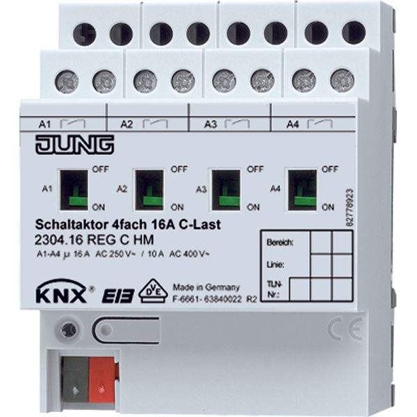
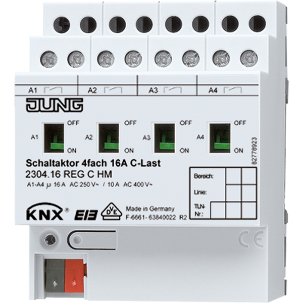
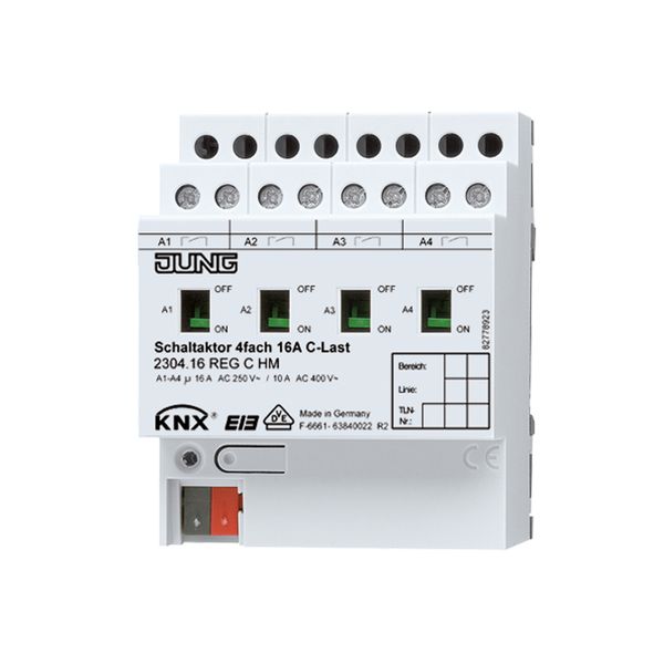
Output module KNX Switch actuator C-load
Order only
Price (excl. VAT):
372,65 €
EAN: 4011377020962
MPN: 2304.16REGCHM
Box: 1
Estimate delivery time at our warehouse (approx.):
4-6 weeks
Technical Information
| Item condition | New |
| Manufacture name | Output module KNX Switch actuator C-load |
| Brand | Jung |
| Categories |
Bus System Devices (KNX/Modbus)
|
| Country of origin* | DE |
| * The actual country of origin may differ depending on the delivery batch. To confirm the specific country of origin, please contact your account manager. | |
| Harmonized System Code | 8537 1098 00 |
| Bus system KNX | Yes |
| With bus connection | Yes |
| Bus system LON | No |
| Bus system KNX radio | No |
| Radio frequent bidirectional | No |
Packing details
| Packing level 1 | 4011377020962 |
Other Technical data
| Mounting method | DRA (DIN-rail adapter) |
| Rated current | 0 A |
| Output power | 0 W |
| Rated operating voltage | 21-32 V |
| Bus system radio frequent | No |
| Bus system Powernet | No |
| Max. switching power | 3680 W |
| Max. number of switching contacts | 4 |
| Width in number of modular spacings | 4 |
| Max. switching current | 16 A |
| Suitable for C-load | Yes |
| Different phases connectable | Yes |
| Local operation/hand operation | Yes |
| With LED indication | No |
| Modular expandability | No |
| Bus module detachable | No |
| Min. depth of built-in installation box | 0 mm |
Downloads
Description
Output module KNX switch actuator.Optimized for handling C-loads.Integrates seamlessly in KNX bus systems for switching and control.;Operates at rated voltage 21-32 V.Rated operating current not defined by standard but supports up to 3680 W max switching power, with a max switching current of 16 A.Width equals 4 modular spacings, built for fast DIN-rail mounting via DRA adapter (DIN).Degree of protection unspecified;verify enclosure robustness on site installations as necessary.Supports up to four controllable contacts max configuration, connectable across different phases directly without restrictions. No LED indicators present;local manual/hand operation supported where required—depends on user interface setup and specific wiring schematics involved in the installation design phase routing/internal harness onboard integration path-location compatibility cross zoning grid-map adjustments-level settings etc


