Register to unlock your exclusive B2B prices and start shopping. Sign up now!
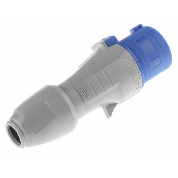
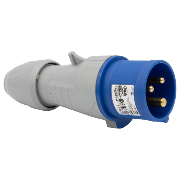
Straight plug P17 - IP44 - 200/250 V~ - 16 A - 2P+E
Order only
Minimal order quantity: 10
Price (excl. VAT):
3,07 €
per pcs
Subtotal: 30,70 €
MOQ: 10
EAN: 3245065551242
MPN: 555124
Package: 1
Box: 10
Pallet: 2760
Estimate delivery time at our warehouse (approx.):
2-4 weeks
Technical Information
| Item condition | New |
| Manufacture name | Straight plug P17 - IP44 - 200/250 V~ - 16 A - 2P+E |
| Brand | Legrand |
| Categories |
CEE Plugs
|
| Country of origin* | TR |
| * The actual country of origin may differ depending on the delivery batch. To confirm the specific country of origin, please contact your account manager. | |
| Harmonized System Code | 8536 6990 00 |
| Number of poles | 3 |
| IEC-amperage | 16 A |
| Connection system | Screwed terminal |
| Degree of protection (IP) | IP44 |
Packing details
| Packing level 1 | 3245065551242 |
| Packing level 2 | 3414970528834 |
| Packing level 3 | 3414970528841 |
Other Technical data
| RAL-number | 5005 |
| Cable entry | Gland nut |
| Material | Plastic |
| Amperage according to UL/CSA (for UL-version) | 0 A |
| Angle of plug | Straight |
| Phase inverter | No |
| Military model | No |
| Clock hour position | 6 h |
| Identification colour | Blue |
| Voltage according to EN 60309-2 | 200 - 250 V (50+60 Hz) blue |
Description
This component is designed for real-time signal amplification and conditioning within low- to mid-power analog circuits. It stabilizes input signals for processing systems, ensuring precision by minimizing noise interference. Common in sensor-based feedback loops or communications modules.
### Electrical Specifications
Operates on a 5V to 15V input power supply range; typical load falls around 20mA at max frequency. Gain levels adjustable up to 40 dB — set by external resistors. Noise figure sub-3dB under standard conditions; dependent on layout and decoupling efficiency. Signal bandwidth spans from DC to 1 MHz, conditioned at ±1% stability over temperature variations (-40°C to +85°C).
### Physical/Mechanical Details
Encapsulated in an 8-pin DIP housing with through-hole mounting compatibility; pin pitch conforming to standard PCB layouts (2.54mm centers). Thermal design optimized via heat dissipation pad beneath middle pins — ensure clearance during soldering process. Total dimensions: L: 10mm x W: 6mm x H:10mm (approx.).
### Key Technical Notes / Limitations:
- Maximum operating voltage limit: Do not exceed +16V nominal supply voltage threshold.
- Subjected to phase distortion >0.1%, noticeable near upper-frequency edges.
- Requires appropriate shielding components when placed near high EMI sources.
- Solder pads need pre-treatment with flux for proper attachment (non-smoothed pins can cause cold joints).


