SICK Relays
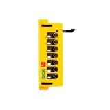
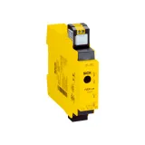
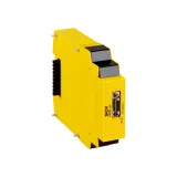
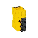
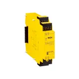
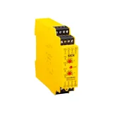
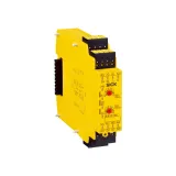
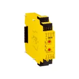
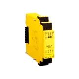
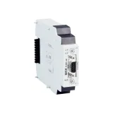
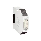
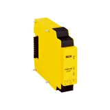
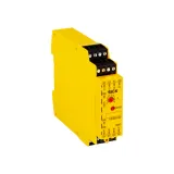
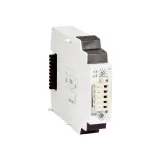
sick relays for control, safety, and isolation
SICK supplies the switching layer that bridges PLC I/O to real-world loads—cleanly, predictably, and with the right footprint for crowded cabinets. Families span compact signal relays for logic, power variants for contactors, and preassembled blocks for quick panel builds. Coils arrive in 12/24 V DC and 110/230 V AC; contact sets range from low-level gold to AgSnO₂ for tougher duties. Clear legends, test levers, and clip-in retainers help technicians fault-find without pulling wiring.
Product range and series overview
You’ll find slim 6–12 mm interface blades for dense I/O marshaling, mid-width bodies with 2CO/3CO for interlocks, and power frames sized for heater valves and small motors. Options include mechanical status flags, LED coil indicators, freewheel diodes or RC snubbers on DC/AC coils, and clip-on jumpers to common the supply bus across a row. For safety paths, force-guided versions pair with external monitoring for EDM and feedback. Projects that standardize on sick industrial relay modules reduce build time by combining coil suppression, indication, and coded sockets in one SKU.
Technical specifications and standards
Contact ratings typically span:
- Signal class: 3–6 A at 250 VAC (AC-15/DC-13), low-level switching down to 10 mA at 5 V with gold flash.
- Power class: 10–16 A at 250 VAC for resistive loads; motor categories per IEC 60947-5-1/4-1 are published by family.
Dielectric strength commonly 2.5–4 kV between coil and contacts; basic/ reinforced insulation is noted on the datasheet. Electrical life runs 100k–200k cycles at rated load; mechanical life lands in the millions. Coil consumption is in the 0.3–1.2 W band (DC) with pull-in at 70–85 % Un and drop-out ≥10 % Un typical. Ambient −25…+55/70 °C depending on density and enclosure. EMC and safety follow EN/IEC 61810 (electromechanical) and—where applicable—UL/CSA files for export.
sick interface relays range and footprints
Slim blades simplify PLC interposing: 6/12 mm widths, 1CO/2CO choices, jump-bridge combs for the coil bus, and push-in terminals for 0.14…2.5 mm². With LED and surge suppression built in, they drop onto 35 mm rail and cut assembly time. Use them between 24 V DC outputs and field devices with inductive kick (valves, small relays) to keep the PLC clean.
sick solid state relays when contacts won’t do
For high-cycle or noisy environments, opto-isolated SSRs switch silently with zero-cross or random-turn-on variants. Typical blocks handle 1–40 A at 24–280 VAC or 24–60 VDC loads, leakage in the mA range, and dv/dt immunity sized for VFD-heavy panels. Heat must be managed—spec heat sinks, check Rθ, and allow airflow. Standards reference IEC 60947-4-3.
Cabling, mounting, and protection
Push-in or screw-cage terminals accept ferruled fine-strand; torque values are printed near cages. Clip-in retainers and coded keys keep parts in the correct base. Coil suppression avoids nuisance trips on adjacent channels; DC coils use diodes or transorbs, AC coils prefer RC networks. Where switching DC inductive loads, fit flyback at the load too—contact life depends on it.
sick din rail relays wiring and accessories
Bodies land on 35 × 7.5 mm rails with end-stops, ID tabs, and bus jumpers. Through-bridging reduces loop wiring; test tabs allow live measurement without disturbing terminations. For tight doors, choose low-height housings; for dusty lines, use clear covers that re-seal after inspection.
Applications and compatibility
- PLC interposing for solenoids, contactors, beacons, and stack lights.
- Signal duplication—one sensor, two destinations—without loading the source.
- Galvanic isolation between noisy field wiring and sensitive inputs.
- Safe-circuit feedback and EDM paths using force-guided contacts.
In HVAC skids, use AgSnO₂ contacts on motorized valves. In packaging, slim blades fan out IO-Link masters to pilot lights and buzzers. For machine tools near coolants, specify sealed housings and stainless spring clips. Where a BOM calls up sick plug-in relays in mixed AC/DC panels, lock coil voltage per row to avoid mis-picks during maintenance.
Integration with other SICK products
Relays sit neatly beside SICK safety controllers and IO blocks. Use interposing on outputs that drive audible/visual alarms; route feedback into safe inputs with monitored contacts. Shield terminations tie into the same earth bar used by sensors and scanners; divider trunking keeps SELV away from mains. When sockets are required for rapid swaps, list sick relay sockets with the correct keying and retainer type.
Selection criteria for B2B clients
Start with load type and duty: resistive, inductive, motor, or lamp. Choose contact material accordingly and check AC-15/DC-13 categories. Decide on coil system (24 V DC is cleanest in PLC panels), then pick LED/suppression options that match your control philosophy. Verify dielectric isolation and creepage/clearance if the relay separates SELV from mains. Size SSRs thermally—continuous current at ambient with enclosure rise—and plan heat sinking. Confirm test levers and flags where diagnostics matter; standardize widths to keep spares lean.
Advantages of working with Bankoflamps
We align relay footprints and coil voltages to your I/O map, then show live EU stock before panel builds are scheduled. Quotes usually land in about an hour with EAN/MPN so contact sets, socket codes, and suppression options don’t drift. Your portal lists lead times, shipment progress, and downloadable price files, with validity windows held to project gates. Approved clients can use post-payment up to 30 days. We consolidate by panel row to cut freight and bench time, and your account manager cross-checks coil voltage, contact form, load category, thermal headroom, rail accessories, and jumper plans against your drawings—so trays arrive shop-ready and wiring goes in once.