Rittal Lighting protection
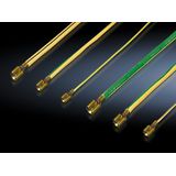
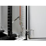
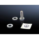
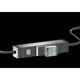
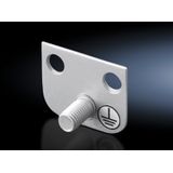
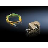
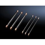
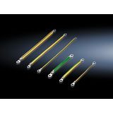
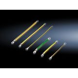
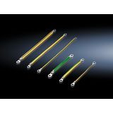
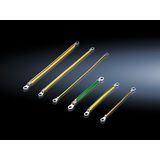
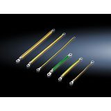
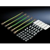
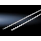
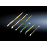
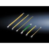
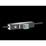
rittal lighting protection for cabinets, poles, and façades
Specifiers choose Rittal protection hardware when LED drivers, PLC I/O, and cabinet power need a clean survival plan against surges and switching spikes. The lineup covers coordinated device layers for service entrances, sub‑boards, and point‑of‑use modules near sensitive loads, with mounting geometry that fits VX25/TS 8/KX/AX/AE platforms without ad‑hoc drilling.
rittal surge protection product range and classes
Type 1 (T1) for service entrances and LPZ 0→1 transitions; spark‑gap or combined designs handle partial lightning impulses Iimp 10/350 µs and quench follow‑current on TN/TT systems.
Type 2 (T2) for sub‑distribution and lighting/control panels; MOV‑based modules specified by In (8/20 µs) and Imax, protecting downstream drivers and control gear from grid‑borne transients.
Type 3 (T3) at the load, with low residual let‑through for LED drivers, gateways, and controllers. Pluggable cartridges speed swap‑out after end‑of‑life indication.
Topologies cover TT/TN/IT networks and protection modes L–N, L/N–PE, or all‑mode where required. Remote‑contact options report status to BMS.
rittal overvoltage protection technical specifications and standards
- System voltage (Uc): select per network (e.g., 275 V~ L–N on 230 V grids; 320–350 V~ where higher tolerance is needed). Control/data SPDs use lower Uc matched to the interface.
- Discharge capability:
- T1: Iimp per pole typically 12.5–25 kA (10/350 µs)
- T2: In commonly 5–20 kA (8/20 µs), Imax up to 40–60 kA
- Protection level (Up): choose so Up stays below the impulse withstand of connected gear (LED drivers often 1.5–2.5 kV). Coordination margin prevents stress aging.
- Short‑circuit coordination: upstream MCB/gG backup values per datasheet; verify assembly SCCR under IEC/EN 61439.
- Wiring rules: keep PE bonds short and straight; total lead length (line + PE) as small as practical with V‑shaped routing to cut inductive overshoot.
- Standards: product selection/testing per IEC/EN 61643‑11; risk and LPZ design per IEC 62305; EMC environment ties to EN 61000‑4‑5 test levels.
- Environment: typical operation −25…+60 °C, storage −40…+80 °C; housings IP20 for DIN‑rail.
Installer note: many LED drivers specify max let‑through—log plate Up values and bond lengths during FAT so maintenance has a baseline
rittal lightning arresters applications and compatibility
- Main boards and exposed services: use T1 at the building/service entrance fed by overhead lines or with external down‑conductors; follow with T2 in lighting sub‑boards.
- Outdoor lighting and poles: place T2 in feeder panels and a compact T3 in pole bases or luminaire junctions to protect driver input stages.
- Retail and plant rooms: fit T2 in the lighting/control panel; add T3 ahead of dimmers, DALI gateways, or Ethernet devices where runs leave the cabinet.
Protect both mains and control paths on mixed systems—mains SPDs at the board plus data‑line devices on DALI/0–10 V/ethernet where cables cross LPZ boundaries.
rittal transient voltage protectors integration with enclosure platforms
Modules mount on TS35 rails and align with standard enclosure punch patterns for cabling. Combine with EMC gland plates and short, wide bonding links to the backplate. Coordinate with RCD/MCB types and contactor/VFD immunity so nuisance trips are avoided. Where cabinets are bayed, mirror SPD locations and labeling so service teams work by habit.
For roof or façade luminaires, specify cartridges accessible from pole bases or gear trays; document Uc/Up and feeder protection upstream.
rittal surge protective devices selection criteria for B2B clients
- Risk and location — external LPS or overhead feeds imply T1 at the service; start at T2 in underground‑fed buildings.
- Uc/Up matching — size Uc to the network and Up below the load’s impulse rating; include margin for aging.
- Discharge current — pick Iimp/In/Imax for earthing quality and grid harshness; industrial parks usually need higher In/Imax.
- Coordination — confirm backup fuse/MCB values and keep lead lengths minimal; choose spark‑gap + MOV combos where follow‑current quenching is essential.
- Signaling & spares — specify remote contacts for BMS alarms and standardize cartridge formats across sites to cut downtime.
Stock planners commonly standardize a T1 for entrances and a T2 for each lighting/control board, with optional T3 kits for driver‑level protection in poles and façades.
Advantages of working with Bankoflamps
We structure commercial terms around your BOM with individual B2B pricing and formal offers, assign a dedicated account manager, and expose live stock across EU warehouses. Quotes typically arrive in about an hour. Orders are placed by EAN/MPN for clean traceability, and price lists remain downloadable and current. You’ll see lead‑time and order‑status tracking plus purchase‑history analytics to consolidate SKUs. For trusted clients we extend post‑payment up to 30 days. We also plan consolidated shipments to lower freight costs, keep pricing stable with validity dates, and support teams in France, the Baltics, Germany, Spain, Italy, Belgium, and the Netherlands.