Rittal Motor Controls and Drives
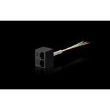
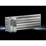
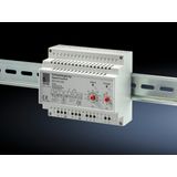
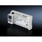
rittal control gear for dependable panel operation
Spec‑grade control assemblies sit at the core of every cabinet: they switch, protect, and interlock loads while keeping maintenance fast and predictable. Rittal hardware gives panel teams finger‑safe mounting, clear diagnostics, and ratings that hold up under real inrush and short‑circuit conditions in plant rooms, OEM machines, and utilities.
rittal relays and contactors product range and series overview
Interface relays handle PLC isolation and small field loads in slim 6–12 mm bodies or plug‑in formats with LED and test buttons. Coil sets cover 24 V DC and 110/230 V AC; contacts SPDT/DPDT up to 10–16 A resistive with AgNi or AgSnO.
Power contactors and starters cover motor and heater duties with AC‑3 ratings from fractional kW up to tens of kW at 400 V. Options include reversing and star‑delta kits, plus mechanical interlocks.
Thermal overload relays pair with contactors for bimetal protection; selectable class 10/20 trip, manual/auto reset, test button, and stop function.
Motor protection circuit breakers (MPCB) integrate magnetic short‑circuit and thermal overload in one device; adjustable ranges, trip indicators, and auxiliary signaling contacts.
Soft‑starter and drive auxiliaries such as bypass contactors, line contactors, and braking units coordinate with upstream protection.
rittal switching devices technical specifications and standards
- Standards: base design to IEC/EN 60947‑1. Motor starters and contactors to IEC/EN 60947‑4‑1 (AC‑3/AC‑1 duty tables, coordination Type 1/2). Control‑circuit devices to IEC/EN 60947‑5‑1.
- Electrical ratings: contactor AC‑3 currents matched to motor power at 400 V; AC‑1 for resistive loads. Short‑circuit coordination specified with upstream gG fuses or MCBs; verify assembly SCCR under IEC/EN 61439 practice.
- Coils: 24 V DC and 110/230 V AC with low heat‑rise designs; DC coils include surge suppression. Inrush/hold VA documented for PSU sizing.
- Terminals: finger‑safe IP20 with screw or spring clamps for 0.5–10 mm² (device‑dependent); dual terminals simplify loop‑through.
- Auxiliaries: front/side‑mount NO/NC blocks, timer add‑ons, and mechanical interlocks; mirror contacts for feedback to PLCs.
- Environment: typical ambient −25…+60 °C; altitude/temperature derating curves apply. Vibration per device family data.
- Diagnostics: trip flags on MPCB/overloads; LED status on relay modules; test buttons for FAT/SAT procedures.
Installation practice: keep control and power segregation in ducting; land PE with serrated hardware to guarantee continuity across painted parts.
rittal motor control gear applications and compatibility
- Conveyors, pumps, fans: MPCB + contactor + thermal overload for classic DOL starting; interlocks for safe reversing.
- Machine sequences: interface relays between PLC outputs and contactor coils; timer modules provide delays for staggered starts.
- Heaters and solenoids: AC‑1 sizing with AgSnO contacts to survive inrush; add RC/diode snubbers on inductive DC loads.
- Drives and soft starters: line and bypass contactors coordinated to device manuals; ensure upstream protection meets the drive’s let‑through limits.
All devices share TS35 mounting and align with Rittal plate/rail geometry for quick swaps and consistent wiring routes.
rittal auxiliary modules integration with enclosure platforms
Auxiliaries clip to contactors and breakers without tools, keeping door cut‑outs minimal. Use TS35 marshalling rows for I/O, then route coil/control on segregated duct. Fit EMC gland plates and 360° shield bonds where VFDs or long analogue runs are present. Document accessory positions and device tags on GA drawings so spares and service are unambiguous.
Where safety interlocks are required, combine positively‑guided auxiliary contacts with door switches and safety relays per the machine risk assessment.
rittal control devices selection criteria for B2B clients
- Duty and coordination — map AC‑3/AC‑1 duty to load type; choose Type 1/2 coordination with fuses/MCBs per short‑circuit levels.
- Control voltage — unify on 24 V DC coils for PLC outputs; reserve 230 V AC coils for retrofit boards.
- Protection concept — MPCB vs fuse‑holder + contactor depending on selectivity and service policy; add thermal overload where required.
- Auxiliary I/O — define NO/NC counts, early‑make/late‑break sequences, and mirror contacts for diagnostics.
- Wiring and footprint — spring vs screw clamps, terminal size vs conductor, and device width vs rail space.
Procurement often standardizes one relay family, one contactor size ladder with matching overloads, and one MPCB range—inventory stays lean and commissioning repeatable.