Register to unlock your exclusive B2B prices and start shopping. Sign up now!
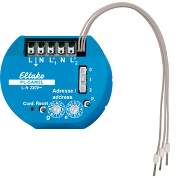
Powerline actuator 2 channels with 2 sensor inputs
Order only
Price (excl. VAT):
95,16 €
EAN: 4010312316672
MPN: 31200001
Package: 1
Estimate delivery time at our warehouse (approx.):
2-4 weeks
Technical Information
| Item condition | New |
| Manufacture name | Powerline actuator 2 channels with 2 sensor inputs |
| Brand | ELTAKO |
| Categories |
Bus System Devices (KNX/Modbus)
|
| Country of origin* | CN |
| * The actual country of origin may differ depending on the delivery batch. To confirm the specific country of origin, please contact your account manager. | |
| Harmonized System Code | 8526 9200 00 |
| Bus system KNX | No |
| With bus connection | Yes |
| Bus system LON | No |
| Bus system KNX radio | No |
| Radio frequent bidirectional | No |
Packing details
| Packing level 1 | 4010312316672, 4010312316672 |
| Packing level 2 | 4010312316672 |
| Packing level 3 | 4010312316672 |
Other Technical data
| Mounting method | Flush mounted (plaster) |
| Rated current | 5 A |
| Output power | 1000 W |
| Rated operating voltage | 230 V |
| Bus system radio frequent | No |
| Bus system Powernet | Yes |
| Max. switching power | 1000 W |
| Max. number of switching contacts | 2 |
| Max. switching current | 5 A |
| Other bus systems | None |
| Suitable for C-load | Yes |
| Different phases connectable | No |
| Local operation/hand operation | Yes |
| With LED indication | Yes |
| Modular expandability | No |
| Bus module detachable | No |
| Min. depth of built-in installation box | 25 mm |
Downloads
Description
Powerline actuator with 2 channels. 53x43mm, 25mm deep for mounting in 58mm switch boxes. Used as impulse switch or relay. 1+1 NO contacts not potential free 5A/250V AC, incandescent lamps 1000 watts. 2 sensor inputs with internal low voltage. Standby loss only 0,5 watt. To control and switch at the same place. Use only potential free switching elements. Internal low voltage applied to the sensor inputs. Two rotary switches are located on the front for address assignment: The left rotary switch defines the group address g with 16 alphabetical values from A to P. The right rotary switch defines the element address e with 16 numerical values from 0 to 15. Above it is a slide switch which acts as a configuration switch with positions 0, 1 and 2. Position 0: Sensor inputs function as pushbuttons (impulse switches). Position 1: Sensor input functions as NC contact (relay). Position 2: A change-over switch is evaluated as a pushbutton. All entries and configurations can also be accessed via the mains using the PC software SIENNA Professional. This means that another configuration can also be set that is not available via the rotary switches: Position 3: Sensor input acts as NO contact (relay inverse). To the left of the rotary switches is a red LED which indicates all activities. Next to it is a reset pushbutton and to the right of that is a service pin. For functions, please refer to the operating instructions. The terminals located above are plug-in terminals for conductor cross-sections of 0.2mm² to 1.5mm². Next to them are three wires with wire end-sleeves for the two control inputs with internal low voltage.

