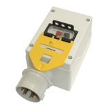
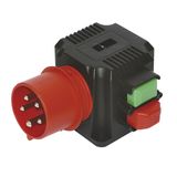
PCE Motor protection circuit-breakers


When motors are involved, you’re not just switching current — you’re controlling risk: overload, phase failure, short-circuit, locked rotor. PCE motor protection circuit breakers combine several protection modes in one device: thermal overload, magnetic short-circuit and manual switching for motor control. Choosing properly means reducing downtime, protecting the motor winding, and ensuring the branch circuit remains within safety limits.
How to Select PCE Motor Starters & Circuit Breakers for Your Motor
For any installation using a motor, you’ll typically need a starter plus protection. The term pce motor starters refers to devices (contactor + overload relay) or combined breakers with built-in starter functionality. Step 1: determine the motor’s full‐load current (FLA) — e.g., a 5.5 kW three-phase motor on 400V ≈ 9 A. Then select a breaker rated slightly above that range, for example an adjustable range 6–12 A. The device should allow thermal setting approx 1.1 × FLA for continuous duty, but trip quickly when overload occurs. Short-circuit magnetic setting might be 10-14 × In. Ensure the PCE product supports your voltage (230/400/480V), ambient temperature (Ta +40 °C) and mounting (DIN rail or panel mount).
Overload Protection & Thermal-Magnetic Breakers from PCE
PCE overload protection means using breakers that integrate a bi-metal thermal element for long-term overloads and a magnetic trip for immediate fault current. The term pce thermal magnetic breakers emphasises this dual mode. For example, a breaker might have a thermal element rated 1.6-2.5 A (adjustable) and magnetic trip at 13 × In. Such devices guard motors against slow grind (overheating) and fast fault (short circuit). When specifying, check trip class (e.g., 10A or 20A) which defines how quickly the unit responds under overload. In rugged environments pick a higher class for motors with high inrush.
PCE Motor Control — Practical Installation & Maintenance Notes
Even though it’s labelled pce motor control, you should think about installation logistics:
- Mounting: Use a 35 mm DIN rail or fixed panel as required. Leave 10 mm side clearance if ambient > 40 °C.
- Terminals: For example, solid copper up to 25 mm² might be supported. Torque typically ~2.0 Nm for 16-63A models.
- Setting: Adjust the thermal dial to motor FLA, note this on panel label. Trip indicator should be visible without panel removal.
- Testing: After commissioning, run motor at full load for 15 minutes; check breaker handle remains ON and temperature of housing < 60 °C above ambient.
- Spares: Keep one identical unit per panel as spare — ensures future replacement without recalibration.
Procurement Checklist for Commercial/Industrial Buyers
For B2B procurement of PCE motor protection devices, use this checklist:
- Confirm specifications: voltage, setting range, breaking capacity (Icu), frame size.
- Order full panel batch at once to ensure consistent front appearance and setting markings.
- Packaging: devices typically shipped in 1-unit boxes; minimum order might be 5 or 10 units depending on model.
- Spare stock: allocate ~5 % extra of each model for future replacement or expansion.
- Documentation: get datasheet, CE certificate and batch/lot number traceability from the distributor.
- Storage: Keep in dry location, ambient 0-+40 °C, avoid stacking heavy boxes on top to protect the mechanism.
Why choose Bank of Lamps
Official European distributor with stock in Latvia
Direct B2B sales across EU (Germany, France, Netherlands, Spain, Baltics)
Full documentation and original manufacturer warranty
Fast dispatch from central warehouse
No project design, no custom solutions — only verified wholesale supply