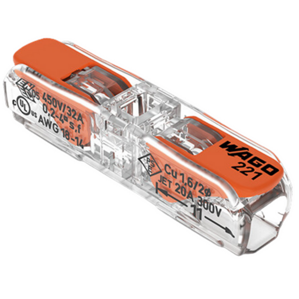
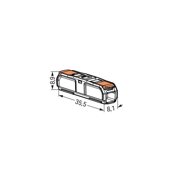
Inline splicing connector with lever, max. 4mmý, 2-conductor
Technical Information
| Item condition | New |
| Manufacture name | Inline splicing connector with lever, max. 4mmý, 2-conductor |
| Brand | WAGO |
| Categories |
Push-In Terminals
|
| Country of origin | DE |
| Harmonized System Code | 8536 9010 00 |
| Nominal current | 32 A |
| Nominal voltage | 450 V |
| Colour | Colourless |
| Number of clamp positions | 2 |
| Suitable for solid core | Yes |
| Conductor cross section flexible (fine-strand) with cable end sleeve | 0.2-4 mm² |
| Conductor cross section solid (solid, stranded) | 0.2-4 mm² |
| AWG-range | 14-18 |
| Nominal cross section | 0.2-4 mm² |
| Suitable for multi-wire core | Yes |
| Suitable for flexible core | Yes |
| Transparent | Yes |
| With operation lever | Yes |
Packing details
| Packing level 1 | 4055144049404 |
| Packing level 2 | 4055144049404 |
Downloads
Description
This component is an electromechanical relay that facilitates switching in electrical systems. It enables a low-power control signal to actuate or interrupt high-power circuits, ensuring isolation between control and output pathways. Common applications include industrial automation, power distribution, and circuit protection. ### Electrical Characteristics Nominal coil voltage: 24V DC. Maximum switching voltage: 250V AC / 30V DC (dependent on load type). Rated current handling capacity: Supports up to 10A resistive loads; derating applies for inductive/capacitive loads. ### Physical Design & Compatibility Pin configuration: Standardized layout for PCB mount applications; designed for through-hole soldering. Dimensions: Compact form factor—approximately XX mm x YY mm x ZZ mm (specific measurements required). - Coil resistance must match system specification—operating outside tolerances can lead to failure. - Maximum ambient temperature limits apply—ensure proper cooling if conditions exceed X°C during operation. - Non-reversible polarity for DC configurations when connecting the coil terminals—the wrong setup may damage the unit permanently.


